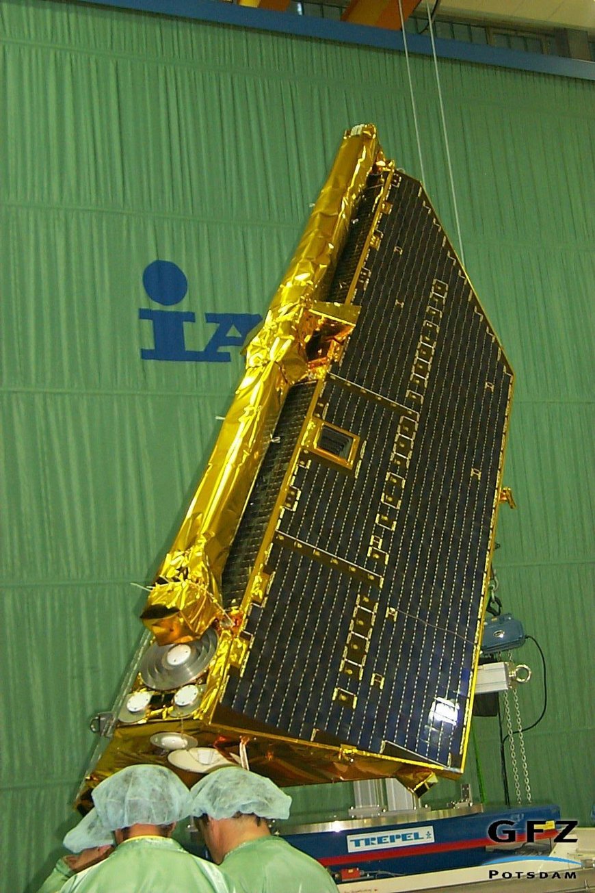
The satellite was designed and manufactured under contract of GFZ by the Daimler Chrysler Aerospace Jena Optronik GmbH (DJO) in an integrated industry effort with Dornier Satellitensysteme GmbH (former DSS, now Astrium) and Raumfahrt und Umwelttechnik GmbH (RST).
The CHAMP satellite has had a robust structure design with fixed solar panels. The primary structure was mainly based on aluminium sandwich panels with an additional kapton foam layer on the outer panels. The shape of the satellite was a compromise with respect to its aerodynamic behavior, accommodation of instruments and subsystems and fitting into the fairing of the launcher.
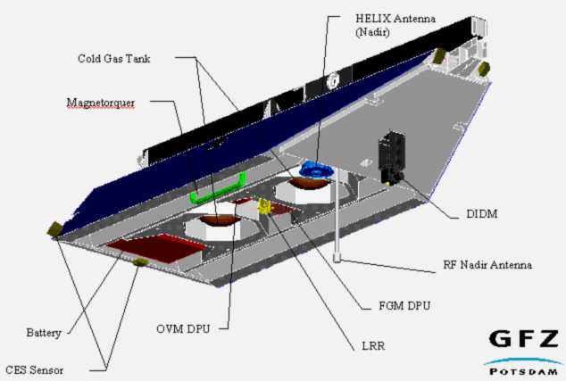
The two solar arrays were symmetrically inclined to the equipment panel with two additional solar panels on the roof side of the spacecraft. The satellite was closed at its aft and front side by sandwich panels of which the aft panel carried the GPS occultation antenna. The front panel carried the digital ion driftmeter and was covered by a conductive aluminium plate in order to avoid electrical charging in the space plasma. The nadir S-band antenna was mounted on short boom beneath the forward compartment, while the zenith S-band antenna was placed on the rear antenna support structure.
The power requirements of the on-board equipment as well as the chosen orbit necessitated about 7m2 of body-mounted solar generator surface. A battery of NiH2-cells ensured the appropriate power supply during eclipses.
Physical parameters of the CHAMP satellite
- Total Mass: 522kg
- Height: 750mm
- Length (with 4044mm Boom): 8333 mm
- Width: 1621 mm
- Area to Mass Ratio: 0.00138m²/kg
For magnetic cleanliness reasons, the magnetometry assembly had to be kept at some distance from the satellite This was achieved by using a deployable boom mounted at the front end of the satellite. The length of the boom was approximately 4m, thus guaranteed that the magnetic strayfield at the location of the Overhauser magnetometer was less than 0.5nT.
Physical parameters of the boom
- Length: 4044mm
- Height: 224 mm
- Width: 224 mm
- Mass: 20 kg
The boom consisted of three segments: the outer part, carried the Overhauser magnetometer, the middle segment with the optical bench on which two star sensor heads and two Fluxgate magnetometers were mounted, and the inner segment with the deployable part of the hinge.
The primary structure housed the accelerometer at the satellite's Center of Gravity (CoG). The surrounding subsystems and especially the two tanks carried gaseous nitrogen were accommodated in such a way that the proof-mass of the accelerometer was coincided with the satellite CoG within 2mm accuracy throughout the whole mission. The laser retro-reflector was within a circle of 5mm located directly below the CoG and the cold gas thrusters were accommodated in such a way that torques were generated with minimum resulting force.
Subsystems
For the Attitude and Orbit Control Subsystem (AOCS), a cold gas propulsion system for attitude and orbit change manoeuvres has been employed. A set of three magnet torquers for pre-compensation of environmental disturbances supported the cold gas propulsion system comprising 14 thrusters. The task was to control the orientation and angular rates within a deadband of ±2° and ±0.1°/s. Star Sensors, GPS, the Fluxgate magnetometer and coarse earth- and sunsensors were used for exact attitude measurement and the calculation of the angular rates.
The Thermal Control Subsystem (TCS) has guaranteed a secure temperature for all instruments and subsystems during all possible space environment conditions. To achieve this, primarily paint with small a/e-values (absorptivity/emissivity), solar cells, Second Surface Mirrors (SSMs) and Multilayer Insulation (MLI) were served for passive thermal control. For critical spots with high demands on temperature stability, active thermal control were pursued by means of heaters.
Power generation, conditioning, distribution and storage were the tasks of the power subsystem. Therefore approximately 7m² of solar cell surface, a combined Power Control and Distribution Unit (PCDU) as well as a NiH2-battery consisted of 10 cells were implemented.
The On-Board Data Handling (OBDH) Subsystem has managed all scientific and housekeeping (H/K) data. In addition, it has had limited autonomous capability of Failure Detection, Isolation and Recovery (FDIR) occurring during data handling. Since most instruments provided scientific as well as H/K-data, the AOCS data handling and software were integrated into the OBDH. The OBDH accepted a 1Hz time reference pulse, derived from the GPS signal and has distributed it to all instruments and attitude sensors. Additionally a clock, synchronised to the GPS 0.1Hz refresh pulse, has maintained the pulse in case of a missing GPS synchronisation. A Mass Memory Unit (MMU) of 1 Gigabit capacity stored all data acquired during observation periods and dumped them, when CHAMP was in visibility of the receiving ground station.
Telecommunication were accomplished by means of the Telemetry, Tracking and Command (TT&C) Subsystem in S-band. This subsystem consisted of a receiver, a transmitter, an encoding/decoding device and two antennas with complementary semi-spherical radiation patterns (one primarily for the Launch and Early Orbit Phase (LEOP) and another for nominal operation).
CHAMP Satellite Subsystem Parameters
Attitude & Orbit Control System (AOCS)
- Three -axis attitude stabilised
- Earth-pointing
- Pointing accuracy < 5°
- Stability: 0,1°/s
Electrical Power
- Power consumption: 150W
- Payload: 50W
- Generation (solar array) 6,9m2
- Storage capacity (NiH2-Battery): 16Ah
Thermal Control
- Average temperature (Equipment platform): +20°C
- Radiator: e = 0,5
- 18 layer flat foil heaters, each 7W
- 60 Sensors Pt 1000
- Power Sensitivity: 3,1°C/10W
Data Handling
- Central Processor Type: P3/1750
- Operating frequency: 12 MHz
- Data Storage:
- RAM/ROM: 1024/256 kByte
- Mass Memory Capacity: 1Gbit
RF Communication
- Uplink (S-Band) Carrier Frequency: 2093,5MHz Data Rate: 4kbit/s
- Downlink (S-Band) Carrier Frequency: 2280 MHz
- Data Rate: 32kbit/s or 1Mbit/s
- RF Output Power: 0,5 or 1,0 W


